Votre message a été envoyé

CURRENT ELECTRICITY
EMF AND POTENTIAL DIFFERENCE
DIFFERENCES
Electromotive force (Emf)
- Emf is the difference in potential between any two terminals of a battery.
- It is a cause.
- Maintain potential differences such as a battery.
- Emf remains constant.
- It is the maximum voltage in the cell.
- Emf refers always to voltage generation.
- Emf is the work done by a source in taking a unit charge once around the complete circuit.
MEASURING THE EMF OF A CELL – IMAGE

Potential difference
- It is the difference in potential between any two points in a closed circuit.
- It is the result.
- Causes current in the circuit as long as there is a potential difference in the circuit (Current will flow).
- The potential difference does not remain constant.
- It is the less maximum voltage. (potential difference is always less than emf).
- Potential difference is due to current path on a component.
- Potential difference is the amount of work done in taking a unit positive charge from one point of a circuit to another.
EMF AND POTENTIAL DIFFERENCE – IMAGE

RESISTANCE AND FACTORS AFFECTING THE RESISTANCE OF A CONDUCTOR
RESISTANCE
The property of a material that confines the progression of electrons is called resistance.
At the point when a potential difference is applied across a conductor an electric field is set up all through the circuit. The free electrons drift or move and they crash into the metal particles and their movement is against. More the impact endured by electrons in a conductor more is the opposition (resistance) presented by the conductor.

REASON FOR RESISTANCE
The fundamental reason for opposition(resistance) is because of the crash (or collaboration) of electrons with the metal particles of the conduit through which they pass.When these electrons slam into them, they move active energy.The electrons lose active energy and slow down.This prompts obstruction.
FACTORS AFFECTING THE RESISTANCE OF A CONDUCTOR
At steady temperature, the opposition(resistance) of a conductor relies upon the accompanying variables
LENGTH
The opposition(resistance) of a is straightforwardly corresponding to the length of the conductor.A long, slim copper wire has higher obstruction than a short,thick copper wire.
For a more extended wire,electrons need to travel more prominent distances so they experience more collisions.More is the length of the conveyor, more is its obstruction.
AREA OF CROSS SECTION (A)
For a uniform conductor, the opposition is contrarily corresponding to the space of cross area.
Thick conductor has least obstruction since electrons can move without impact or catch by an atom.
Thin conductor has greatest obstruction because electrons have less free ways to course through the conductor and experience more resistance.
NATURE OF THE MATERIAL
Opposition(resistance) of a conductor additionally relies upon the idea of the material in which it is made up and furthermore its size and shape.
If the material has bigger molecules there should be more electrons accessible and when it is firmly stuffed then the electrons will have more incessant impacts and the obstruction will increase.
Electrons can stream uninhibitedly through a copper wire yet can’t stream effectively through a steel wire of a similar size and shape.
WHEN THE TEMPERATURE IS INCREASED
Obstruction(resistance) of wire resistors and different parts regularly change with temperature.
On expanding the temperature, the electrons begin to vibrate and the sufficiency of vibration of particles increases. Due to their expansion in energy, crashes(collisions) become continuous and,more is the opposition presented by the conductor.
RESISTANCE AND RESISTIVITY – NUMERICAL

ELECTRICAL RESISTIVITY AND CONDUCTIVITY
INTRODUCTION
Electrical resistivity is a measurement of how vehemently a substance resists current passage through it.Based on the resistivity levels and how the materials behave in electrical circuits, substances can be categorized as conductors, semiconductors, or insulators.There are many situations in real life when the reciprocal relationship between electrical resistivity and conductivity might be used.
Silver and copper, which have low resistivity values, are frequently used in electrical wiring, whereas manganin, an alloy with high resistivity, is utilized in the heating components of electric heaters.Electric current flow through a substance is measured by its electrical conductivity.Let’s talk about resistivity and conductivity in this context.
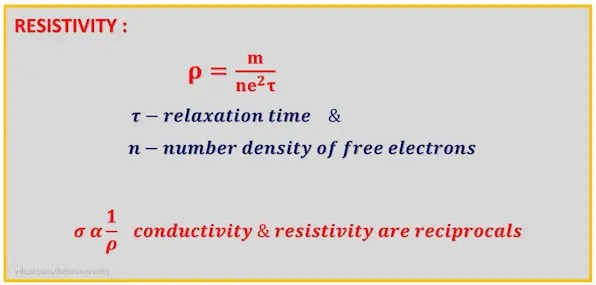
ELECTRICAL RESISTIVITY

RESISTIVITY VALUE OF AN ALLOY

RESISTIVITY – S.I UNIT

RESISTIVITY – DIMENSIONAL FORMULA

RESISTIVITY APPLICATIONS IN REAL-LIFE SITUATIONS
Resistivity has several scientific and technological uses, including electrical wiring, heating elements, resistors, semiconductors, and geophysics.
Electrical wiring
To guarantee that the conductors have the proper resistance to effectively transport electrical power, resistivity is employed in the construction of electrical wires and cables. (Wired electrical system)
Due to their low resistivity values, copper and silver are the two materials that are most frequently used for wire systems. Silver and copper have respective resistivity of 1.6X10⁻⁸ ohm metres and 1.68X10⁻⁸ ohm metres. They are regarded as the greatest electrical conductor because of their low resistivity values.
Heating element
Electric stoves, toasters, ovens, and other appliances’ heating elements are often designed using resistivity.Compared to their component, Alloys have higher resistivity than their constituent metals, used for their ability to generate heat when an electric current flows through that.
Resistors
To obtain the appropriate degree of resistance in a circuit, resistors are constructed with particular resistivity values.
Semiconductors
These resistivity values are needed while developing semiconductors.Electronic devices including diodes, transistors, and integrated circuits employ semiconductors.
ELECTRICAL CONDUCTIVITY
Conductivity is the inverse of resistivity.
How strongly a material resists or conducts electric current. (OR)
Ability of a conductor to conduct.
CONDUCTIVITY- S.I UNIT AND DIMENSIONAL FORMULA

RELATION BETWEEN CURRENT AND DRIFT VELOCITY

RATIO OF MAXIMUM TO MINIMUM RESISTANCE
INTRODUCTION
The idea of series and parallel combinations of resistors, as well as their ratios, are utilised in physics and are crucial to understanding a number of phenomena, including electromagnetic induction, electrical power, and Ohm’s law. In computer science, the design of digital circuits and microprocessors makes use of this idea.
Let’s talk about the characteristics of series and parallel combinations, a straightforward mathematical formula for calculating the ratios of series and parallel resistor combinations, and the ideas behind these concepts, which are used in a variety of fields, including engineering, science, technology, electronics, computer science, battery design, ballistics, and telecommunications, among others.
CHARACTERISTICS OF A PARALLEL & SERIES CIRCUIT

| SERIES CIRCUIT | PARALLEL CIRCUIT |
| *Current passing through each resistors is the same *Net effective resistance in the case of series combination is the sum of the individual resistances Rs=R1+R2+R3 *The applied voltage is the sum of the potential difference formed across the individual resistors. *The net effective resistance is higher than the highest resistance in the circuit, |
*Current passing through them is not the same. *The reciprocal of the net effective resistances in the case of parallel combination is equal to the sum of the reciprocal of their individual resistances. *The potential difference across each resistor is the same *The net effective resistance is lesser than the least value of resistance in the circuit. |
Numerical on ratio of maximum to minimum resistance
QUESTION – 1
What is the ratio of maximum to minimum resistance in a circuit made up of two identical resistors?
SOLUTION

RESISTORS CONNECTED IN SERIES TO GET MAXIMUM RESISTANCE

Question – 2
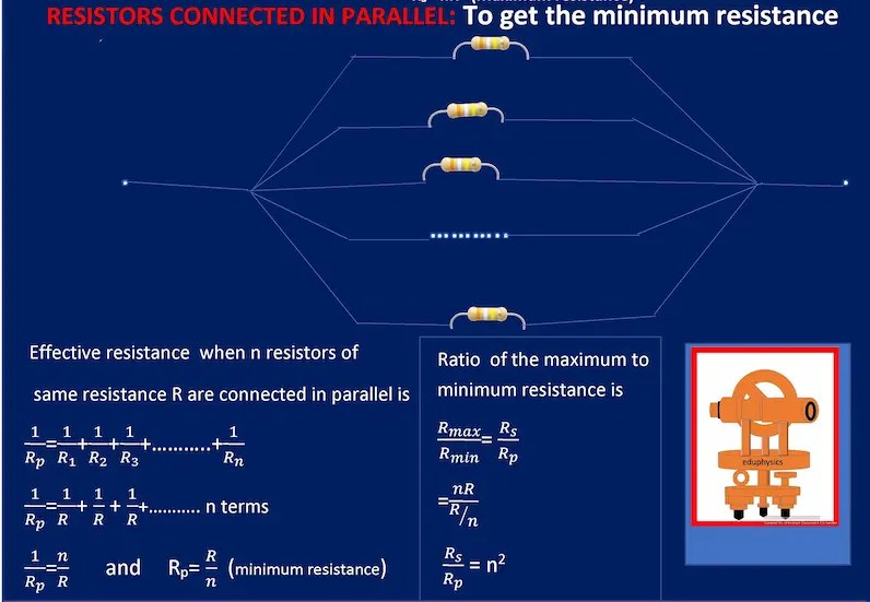
What is the ratio of maximum to minimum resistance in a circuit made up of ‘n’ identical resistors?
Solution
SERIES COMBINATION OF RESISTORS- MAXIMUM RESISTANCE

RESISTORS CONNECTED IN PARALLEL- MINIMUM RESISTANCE
CONCLUSION
For the purpose of building and assessing electrical circuits, it is essential to understand the concepts of series, parallel, and resistor combinations, as well as their ratio.A straightforward mathematical method may be used to determine the ratio of maximum to minimum resistance for identical resistors.Fundamental to the study of electrical engineering, this idea has significant real-world implications for building and improving electronic circuits.Additionally, it plays a crucial role in the design and optimization of battery systems, particularly for those used in high voltage and high capacity applications like portable electronics, renewable energy systems, and electric vehicles.
This idea is applied to the design of telephone and satellite systems as well as other communication networks in telecommunication.It is employed in the creation and evaluation of many different types of sensors, including temperature and precision sensors.Typically, this idea is used in various fields like physics, electronics, computer science,telecommunications and sensing technologies.
CLASSIFICATION OF MATERIALS BASED ON THEIR RESISTIVITY VALUES

EFFECT OF TEMPERATURE ON RESISTIVITY

INTERNAL RESISTANCE OF A CELL/BATTERY
INTERNAL RESISTANCE
Internal resistance is the electrical resistance inside batteries and power supplies that can limit the potential difference that can be supplied to an external load. [OR]
It is the resistance offered by the electrolyte of a cell to the flow of current between its electrodes.

Internal resistance of a cell is offered by the electrode and electrolyte which oppose the current flow inside the cell. The higher the internal resistance, the less current the battery is capable to provide.
A freshly prepared cell has low internal resistance and this increases with ageing. Batteries that have high internal resistance will take more time to fully charge.
INTERNAL RESISTANCE VALUE OF A DRY CELL AND LECLANCHE CELL
High resistances cause the battery to heat up excessively and voltage output to drop under high demand. The internal resistance of a dry cell varies from about 0.5 to 1.0 ohms.The internal resistance of a Leclanche cell is about 5 to 10 ohms.
PRACTICAL IMPORTANCE OF INTERNAL RESISTANCE OF A CELL
The concept of internal resistance is useful for analyzing many types of electrical circuits. The strength of the current obtained from a cell depends not only on the emf but also on the internal resistance. Elevated internal resistance measurements can be a sign that a cell is nearing failure.
INTERNAL RESISTANCE – FORMULA

HOW TO CALCULATE INTERNAL RESISTANCE OF A CELL/BATTERY?

INTERNAL RESISTANCE OF A CELL USING POTENTIOMETER EXPERIMENT


CONCLUSION
A Leclanche cell’s internal resistance is significant because it affects the overall performance of the battery or cell. When a load is connected to the cell, the internal resistance causes a voltage drop across the cell, reducing the amount of voltage available to the load, which can result in a slower response time or lower power output.
A cell’s internal resistance influences its ability to deliver current to a load. When compared to used cells, freshly prepared cells have lower internal resistance.Did you measure the internal resistance of a cell in your laboratory?
KIRCHHOFF’S CURRENT AND VOLTAGE LAWS
KIRCHHOFF’S CURRENT LAW (KCL)
INTRODUCTION
Kirchhoff’s first law, generally known as the conservation of charge, asserts that « the algebraic sum of current at any junction in an electrical circuit is zero. »We may find any inconsistencies or deviations in circuit values by applying this formula at various junctions in a circuit.This rule is important to modern measuring techniques and is frequently applied in electrical engineering.
This rule determines how current is dispersed in a circuit, is vital in electrical circuit design, and is critical in recognizing defects or irregularities in electrical systems.This equation is a handy tool for solving a wide range of electrical circuit difficulties.In this topic, let us look into this law.
KIRCHHOFF’S FIRST LAW
This law is based on LAW OF CONSERVATION OF CHARGES.This law is widely used in electrical engineering.The current law relies on the fact that the net charge in the wires and components is constant.The current law is applicable to any lumped network irrespective of the nature of the network
KIRCHHOFF’S FIRST LAW – STATEMENT
Kirchhoff’s first law states that « IN AN ELECTRIC CIRCUIT, THE ALGEBRAIC SUM OF CURRENT AT ANY JUNCTION IS ZERO ».
TOTAL CURRENT ENTERING A JUNCTION EQUALS TOTAL CURRENT LEAVING THE JUNCTION.
Current flowing towards the junction is taken as POSITIVE and current flowing away from the junction is taken as NEGATIVE.
KIRCHHOFF’S FIRST LAW-IMAGE

KIRCHHOFF’S FIRST LAW- EXAMPLE

KIRCHHOFF’S VOLTAGE LAW (KVL)
INTRODUCTION
Kirchhoff’s second law, generally known as the law of conservation of energy, says that « in an electrical circuit, the algebraic sum of all potential differences along a closed loop is zero. »This rule is important in the construction of electrical circuits.Engineers may verify that the voltage needs of various components are satisfied by applying this law in crucial circuits.
This rule is often applied in mesh analysis, a technique for solving circuits with numerous loops.Engineers may use this rule to better understand voltage distribution, assess complicated circuits, measure voltage, and verify correct circuit performance.
KIRCHHOFF’S SECOND LAW OR VOLTAGE LAW
Kirchhoff’s subsequent(second) law is otherwise called Voltage law (OR) Loop law.
This law depends on LAW OF CONSERVATION OF ENERGY.
Kirchhoff’s subsequent law expresses that » THE ALGEBRAIC SUM OF ALL THE POTENTIAL DIFFERENCES ALONG A CLOSED LOOP IS ZERO ».
CONVENTIONS
- Accept any course (direction) as the heading of traversal (direction of traversal). (Either clockwise or anticlockwise)
- EMF of the cell is POSITIVE in the event that the bearing of the crossing (direction of the traversal) is from its NEGATIVE terminal to POSITIVE terminal. (NPP)
- EMF of the cell is NEGATIVE assuming the heading of the crossing (direction of the traversal) is from its POSITIVE terminal to NEGATIVE terminal of the battery. (PNN)
- The IR item is taken as POSITIVE on the off chance that the resistor is crossed a similar way as the expected to be current. (If the resistor is traversed in the same direction as the assumed current.)
KIRCHHOFF’S SECOND LAW
EXPLANATION

KIRCHHOFF’S LAW NUMERICAL


METER BRIDGE – NUMERICAL


 Chat With Us
Vous devez être connecté pour poster un commentaire.