
NEET PHYSICS
PHYSICS PRACTICAL
Zero Error in Screw Gauge: Positive and Negative Error
Learn how to identify, calculate and correct
zero error in a screw gauge, including
positive zero error, negative zero error, zero correction,
least count and practical measurement examples.
Quick Answer
Zero error in a screw gauge occurs when the
zero of the circular scale does not coincide with the reference
line when the anvil and spindle are brought into proper contact.
The two important types are
positive zero error and
negative zero error.
Zero Correction = − Zero Error
Thus, a positive zero error requires a negative correction,
while a negative zero error requires a positive correction.
Micrometer Screw Gauge

A precision instrument used to measure very small dimensions,
such as the diameter of a thin wire or the thickness of a sheet.
Screw Gauge — Physics Practical

precision measurements of small dimensions.
What Is Zero Error in a Screw Gauge?
Before measuring an object, the anvil and spindle of a screw gauge
are brought gently into contact. Ideally, the
zero of the circular scale should coincide with the
reference line on the sleeve.
If the two zeros do not coincide when the measuring faces are
properly closed, the instrument has a
zero error.
Zero error is an instrumental error. It must be
determined before taking measurements so that the observed reading
can be corrected.
Key idea:
Zero error belongs to the measuring instrument. Determine it
before measuring the object and apply the corresponding zero
correction to the observed reading.
Important Parts of a Screw Gauge
| Part | Function |
|---|---|
| Anvil | Fixed measuring surface against which the object is placed. |
| Spindle | Movable measuring surface that approaches the anvil. |
| Sleeve / Main Scale | Provides the main-scale reading. |
| Thimble / Circular Scale | Rotates with the spindle and provides the circular-scale reading. |
| Ratchet | Helps apply approximately uniform pressure while taking a measurement. |
Least Count of a Screw Gauge
The least count is the smallest measurement that
can be measured reliably by the instrument.
Least Count =
Pitch ÷ Number of divisions on the circular scale
For example, if the pitch is 1 mm and the
circular scale has 100 divisions:
Least Count = 1 ÷ 100 = 0.01 mm
Types of Zero Error in Screw Gauge
No Zero Error
The zero of the circular scale coincides with the reference
line when the measuring faces are properly closed.
Zero Error = 0
Positive Zero Error
The circular-scale zero is displaced from the reference line
in the positive-error configuration.
Zero Error = +e
Negative Zero Error
The circular-scale zero is displaced from the reference line
in the negative-error configuration.
Zero Error = −e
No Zero Error in a Screw Gauge
When the anvil and spindle are brought into proper contact and the
zero of the circular scale coincides with the reference
line, the screw gauge has no zero error.
No Zero Error
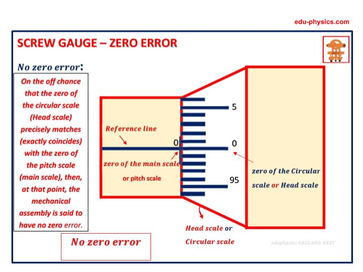
The zero of the circular scale coincides with the reference line
when the measuring faces are properly closed.
Zero Error = 0
Zero Correction = 0
Positive Zero Error in Screw Gauge
A positive zero error occurs when, after the measuring faces are
properly brought into contact, the zero of the circular scale
does not coincide with the reference line and the scale is in the
positive-error configuration.
Positive Zero Error

The zero of the circular scale is displaced from the reference
line in the positive-error configuration.
Positive Zero Error Formula
If the coinciding circular-scale division is
n and the least count is
LC:
Positive Zero Error = +n × LC
Zero Correction = −n × LC
Worked Example
Suppose the second division of the circular scale coincides with
the reference line and the least count is
0.01 mm.
Zero Error = +2 × 0.01 mm
Zero Error = +0.02 mm
Zero Correction = −0.02 mm
Result:
The correction is −0.02 mm, so 0.02 mm is
subtracted from the observed reading.
Negative Zero Error in Screw Gauge
A negative zero error occurs when the zero of the circular scale
is displaced in the opposite direction from the positive-error
configuration when the measuring faces are properly closed.
Negative Zero Error

The zero of the circular scale is displaced from the reference
line in the negative-error configuration.
Negative Zero Error Formula
For a circular scale containing N divisions,
if the n-th division coincides with the reference
line, the number of divisions between that position and the
circular-scale zero is:
Number of remaining divisions = N − n
Negative Zero Error = −(N − n) × LC
Zero Correction = +(N − n) × LC
Worked Example
Suppose the circular scale has 100 divisions,
the 97th division coincides with the reference line, and the
least count is 0.01 mm.
N − n = 100 − 97 = 3 divisions
Error magnitude = 3 × 0.01 mm
Zero Error = −0.03 mm
Zero Correction = +0.03 mm
Result:
The correction is +0.03 mm, so 0.03 mm is
added to the observed reading.
Screw Gauge Reading and Zero Correction
A screw-gauge measurement is obtained from the main-scale
contribution and the circular-scale contribution.
Observed Reading =
Main Scale Reading + Circular Scale Reading
After determining the zero error, apply the zero correction:
Corrected Reading =
Observed Reading + Zero Correction
Zero Correction = − Zero Error
Important:
Zero error and zero correction have equal magnitude but opposite
signs.
Positive vs Negative Zero Error
| Condition | Zero Error | Zero Correction | What to do |
|---|---|---|---|
| No zero error | 0 | 0 | No correction required. |
| Positive zero error | +e | −e | Subtract the error magnitude. |
| Negative zero error | −e | +e | Add the error magnitude. |
How to Find Zero Error in a Screw Gauge
- Clean the measuring faces.
Make sure the anvil and spindle are free from dust and other
particles. - Bring the measuring faces into proper contact.
Use the ratchet carefully and avoid excessive force. - Observe the reference line.
Check the position of the circular-scale zero relative to the
reference line. - Identify the coinciding division.
Determine which circular-scale division aligns with the
reference line. - Determine the sign.
Decide whether the configuration represents positive or
negative zero error. - Calculate the zero error.
Use the least count and the appropriate number of divisions. - Calculate the zero correction.
Always remember:
Zero Correction = − Zero Error.
How to Minimize Errors in a Screw Gauge
Accurate screw-gauge measurements require careful handling of the
instrument and correct experimental technique.
- Use a clean screw gauge in good working condition.
- Clean the anvil and spindle before taking measurements.
- Make sure the anvil and spindle are properly aligned.
- Avoid applying excessive force to the object.
- Use the ratchet carefully to obtain consistent contact pressure.
- Check the zero error before measuring the object.
- Take repeated readings and determine the average when required.
- Place the object properly between the anvil and spindle.
Practical tip:
Always determine the zero error before recording the actual
measurement of the object.
Worked Numerical Example
Question
A screw gauge has a pitch of 1 mm and its
circular scale has 100 divisions. When the
measuring faces are brought together, the 97th division of the
circular scale coincides with the reference line.
Determine the zero error and zero correction.
Solution
First calculate the least count:
LC = Pitch ÷ Number of circular-scale divisions
LC = 1 ÷ 100 = 0.01 mm
Number of divisions remaining:
N − n = 100 − 97 = 3
Zero Error = −3 × 0.01 mm
Zero Error = −0.03 mm
Zero Correction = +0.03 mm
Final Answer:
Zero error = −0.03 mm;
zero correction = +0.03 mm.
Common Mistakes Students Make
1. Confusing Error and Correction
Zero correction has the opposite sign to zero error.
Correction = − Error
2. Ignoring Least Count
The magnitude of zero error depends on the least count of the
instrument.
3. Counting the Wrong Divisions
For negative zero error, carefully determine the divisions
remaining to reach the circular-scale zero.
CBSE & NEET Practice Questions
1. When the zero of the circular scale coincides with the
reference line, the zero error is:
A. Positive
B. Negative
C. Zero
D. Equal to the pitch
2. If the zero error of a screw gauge is +0.04 mm,
the zero correction is:
A. +0.04 mm
B. −0.04 mm
C. +0.08 mm
D. 0 mm
3. A screw gauge has a pitch of 1 mm and 100 divisions on
its circular scale. Its least count is:
A. 1 mm
B. 0.1 mm
C. 0.01 mm
D. 100 mm
4. If the zero error is −0.03 mm, the zero correction is:
A. −0.03 mm
B. +0.03 mm
C. −0.06 mm
D. 0 mm
Zero Error — Quick Revision
Least Count =
Pitch ÷ Number of Circular Scale Divisions
Zero Correction = − Zero Error
Corrected Reading =
Observed Reading + Zero Correction
| Concept | Key Point |
|---|---|
| Zero error | Error present when the measuring faces are properly closed. |
| Positive error | Zero correction is negative. |
| Negative error | Zero correction is positive. |
| Zero correction | Always the negative of zero error. |
Frequently Asked Questions
What is zero error in a screw gauge?
Zero error is the error shown by a screw gauge when its measuring
faces are properly closed but the zero of the circular scale does
not coincide with the reference line.
What is positive zero error?
Positive zero error occurs when the circular-scale zero is
displaced from the reference line in the positive-error
configuration.
What is negative zero error?
Negative zero error occurs when the circular-scale zero is
displaced from the reference line in the negative-error
configuration.
What is the relation between zero error and zero correction?
Zero Correction = − Zero Error
Why is zero correction necessary?
Zero correction compensates for the instrumental error so that
the corrected measurement is closer to the actual value.
What is the least count of a screw gauge?
The least count is the smallest measurement that can be measured
by the instrument. It is calculated by dividing the pitch by the
number of divisions on the circular scale.
Final Takeaway
For screw-gauge questions, first determine the
least count, identify the
zero error, and then apply the correction with
the opposite sign.
Zero Correction = − Zero Error
Mastering this relationship prevents one of the most common
mistakes in screw-gauge practical measurements.
NIOS Physics Practical Connection
Understanding zero error, positive error and negative error in a screw gauge is essential for accurate measurements in Physics practicals. Explore the complete collection of NIOS Class 12 Physics practical experiments, including measurement techniques, observations, calculations and viva questions, on eduPhysics.
Explore: NIOS Class 12 Physics Practical Experiments Master Hub
Leave a Reply