
eduPhysics/class XII Physics Practical/NEET/JEE/CBSE/NIOS
Take a fresh 1.5 V cell and put a voltmeter across it. It reads 1.5 V. Now connect a small bulb and watch the voltmeter again. The reading drops, say to 1.2 V. Nobody removed any chemistry from the cell, so where did the missing 0.3 V go?
It was lost inside the cell itself, in a hidden resistance that every real cell carries. Physicists call it internal resistance. In this post you will see what it is, why it matters (from phone batteries to UPS systems), and how to measure it with a potentiometer, with a full set of observations and worked numbers from a real laboratory run.
In one line: a real cell is an ideal source of emf (ε) in series with a small resistor (r). The current you draw has to pass through r, and the volts it eats are never delivered to your circuit.
1. What is internal resistance?
Internal resistance (r) is the resistance offered by the electrodes and the electrolyte of a cell to the flow of current inside the cell. It is measured in ohms (Ω).
It comes from several sources:
- the electrolyte, which has to carry ions between the electrodes
- the electrode material and the surface where the reaction occurs
- the gap between the electrodes
- products of the chemical reaction that build up as the cell is used (polarisation)
The higher the internal resistance, the less current the cell can deliver, and the more energy is wasted as heat inside the cell.
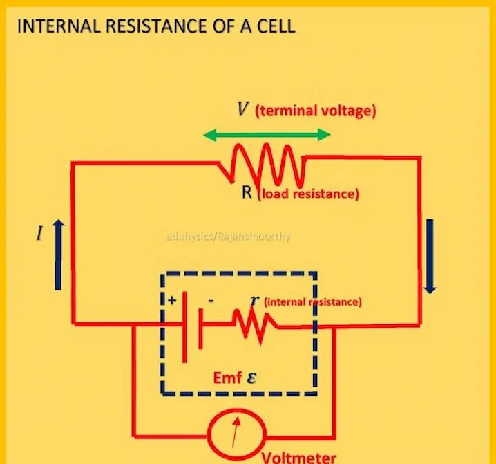
2. Reading the circuit diagram
The diagram shows a cell connected to a load resistance R, with a voltmeter connected across the cell terminals.
- ε (emf) is the ideal source inside the dashed box.
- r is the internal resistance, in series with ε and drawn inside the same dashed box.
- R is the external load resistance.
- I is the current, flowing out of the positive terminal, through R, and back to the negative terminal.
- V is the terminal voltage that the voltmeter reads.
Applying Ohm’s law to the complete loop:
- Current: I = ε / (R + r)
- Terminal voltage: V = IR = ε − Ir
- Lost volts: v = Ir, so ε = V + Ir
Rearranging gives the formula we use in the lab:
r = (ε − V) / I = R (ε − V) / V
What happens at the extremes?
| Situation | Current drawn | Terminal voltage |
|---|---|---|
| Open circuit (no load) | I = 0 | V = ε (maximum) |
| Normal load R | I = ε / (R + r) | V = ε − Ir (less than ε) |
| Short circuit (R = 0) | I = ε / r (maximum) | V = 0 |
The short-circuit current is why a small r is dangerous in a short circuit: a cell with ε = 1.5 V and r = 0.5 Ω can push 3 A through a wire, and the heat can be severe.
3. EMF vs potential difference: do not mix them up

Memory hook: EMF is what the cell can give. Potential difference is what you actually get.
Exam trap: V < ε holds only while the cell is discharging. While a cell is being charged,V = ε + Ir, so the terminal voltage is greater than ε.
4. How big is r? Typical values and what changes it
The value of r depends on the type, size and condition of the cell. As rough orders of magnitude:
| Cell / battery | Typical internal resistance |
|---|---|
| Car lead-acid battery | a few milliohms |
| Li-ion cell (such as 18650) | tens of milliohms |
| Fresh alkaline AA | a fraction of an ohm |
| Zinc-carbon dry cell | a fraction of an ohm to about an ohm; rises quickly with use |
| Wet Leclanché cell (laboratory) | a few ohms (the experiment below gave about 7 Ω) |
What makes r larger?
- Age and use: a freshly prepared cell has low r, and r rises as the cell ages or runs down.
- Temperature: cold slows the ions, so r goes up.
- Electrode separation: a larger gap means more electrolyte for the ions to cross, so r goes up.
- Electrode area: a larger area means lower r.
- Electrolyte concentration: a more dilute electrolyte means higher r.
- Heavy current: polarisation builds up and the apparent r rises.
A wet Leclanché cell in the laboratory has widely spaced electrodes in a large jar of electrolyte, which is why its r is much larger than that of a compact sealed dry cell.
5. Why internal resistance matters in real life
- Heat: the power wasted inside the cell is I²r. A high-r cell heats up when it supplies large currents.
- Voltage sag: your phone can shut down at “20%” in the cold because r rises, the voltage dips under load, and the device thinks the battery is empty.
- Efficiency and charging: a high-r cell wastes more energy as heat while charging and discharging.
- Battery health: engineers track the rise in r to decide when a battery pack has aged. UPS systems and electric vehicles use low-r cells so they can deliver large currents quickly.
- Maximum power transfer: a cell delivers maximum power to a load when R = r. At that point only half of the total power reaches the load, so the efficiency is 50%.
6. Method 1: the quick method (load and voltmeter)
- Measure the open-circuit voltage of the cell with a high-resistance voltmeter. This is ε.
- Connect a known load R and measure the terminal voltage V.
- Find the current I = V / R.
- Calculate r = (ε − V) / I.
Common Mistake: writing r=V/I. That gives the total load resistance, not the internal resitance.Internal resistance comes from the lost volts,(ε − V), divided by the current.
The quick method is fine for rough work, but a voltmeter draws a little current, so it never reads the true emf. The potentiometer avoids this problem.
7. Method 2: the potentiometer experiment (the accurate method)
7.1 Why a potentiometer?
At the balance point (null point) the galvanometer shows no deflection, which means no current flows through the cell being tested. Its reading is therefore the true emf, and not a reduced terminal voltage. The same wire can then be used to measure the terminal potential difference when the cell is connected to a known resistance R.
7.2 Theory and derivation
A uniform wire with a steady current has a potential drop proportional to length, so the potential drop per unit length (the potential gradient) is a constant, k.
- With key K open (no load), the cell is in open circuit and balances at length l₁: ε = k l₁
- With key K closed (resistance R connected across the cell), the terminal voltage balances at length l₂: V = k l₂
Dividing: ε / V = l₁ / l₂
The current through the cell is I = V / R, and ε = V + Ir, so:
ε / V = (R + r) / R = l₁ / l₂
Solving for r:
r = R (l₁ − l₂) / l₂
In the table, R is the known resistance taken from the resistance box.
7.3 Apparatus (as labelled in the photograph)

| Label | Component | Role |
|---|---|---|
| Bt | Battery or battery eliminator (driver) | Sends a steady current through the potentiometer wire. Its emf must be greater than that of the cell under test. |
| K₁ | Plug key | Switches the primary circuit on and off |
| Rh | Rheostat | Adjusts the current, and so the potential gradient |
| A, B | Ends of the potentiometer wire | The positive terminal of the driver and of the cell must go to A |
| J | Jockey | Slides along the wire to find the null point |
| G | Galvanometer | Detects the null point |
| HR | High resistance | Protects the galvanometer from large currents |
| L | Leclanché cell | The cell whose emf and internal resistance are measured |
| K₂ | Plug key (the box marked “for terminal p.d”) | Open: gives emf. Closed with R connected: gives terminal p.d |
| R | Resistance box | Gives the known resistance R |
7.4 The circuit

The circuit has two parts.
- Primary circuit: the driver battery Bt, key K, rheostat Rh and the potentiometer wire form a series loop. This loop creates the potential gradient along the wire.
- Secondary circuit: the cell L, the high resistance HR, the galvanometer G and the jockey J, with the resistance R and key K across the cell. This loop finds the balance points.
The diagram shows a four-wire potentiometer, with 100 cm per wire and a total length of 400 cm. The balance points in our observations (about 226 to 233 cm) lie well within this range.
7.5 Procedure
- Draw the circuit diagram and connect the components. Join the positive terminals of the driver battery and the cell to the same end, A.
- Close the primary key and adjust the rheostat so that the balance point of the cell falls on the wire, comfortably before the far end.
- With the secondary key removed (no shunt), place the jockey at different points, find the null point with the galvanometer, and note the balancing length l₁.
- Take out a convenient resistance R from the resistance box and insert the key to connect R across the cell (the shunt). Find the new null point and note l₂.
- Remove the key immediately after taking each reading. Repeat for at least three different values of R.
- Calculate r for each row using r = R (l₁ − l₂) / l₂ and take the mean.
7.6 Observations

7.7 Worked calculation
- l₁ − l₂ = 230.1 − 72.0 = 158.1 cm
- (l₁ − l₂) / l₂ = 158.1 / 72.0 = 2.196
- r = 2.196 × 3.3 = 7.25 Ω
The emf and the terminal voltage are proportional to l₁ and l₂, so the ratio l₁ / l₂ tells us how much of the emf is lost inside the cell. In row 2, V is only 72.0 / 230.1 = 31% of ε. The load of 3.3 Ω is smaller than r, so most of the emf is dropped inside the cell.
7.8 A teacher’s observation on these results
The three values of r (5.96, 7.25 and 8.28 Ω) are not equal. Their spread is about 2.3 Ω, around ±17% of the mean. In an ideal experiment r would be constant. Notice also that r rises as R rises, while we might have expected it to be larger at the smaller R (which draws more current and causes more polarisation). A trend like this usually means the cell’s condition changed during the experiment, for example because the key stayed inserted too long between readings, which weakens the cell. In your own write-up, comment on this and explain how you would reduce it: keep the key inserted only for the time needed to find l₂, and wait for the cell to recover between readings.
7.9 Precautions
- All connections must be tight and the plug keys clean.
- The positive terminals of the driver battery and the cell must go to the same end (A), otherwise no null point exists.
- The emf of the driver battery must be greater than the emf of the cell.
- Keep the key K inserted only for a short time, since a continuous current changes the cell.
- Do not press the jockey hard or drag it along the wire. Use a light touch.
- Keep the high resistance HR in the circuit until the galvanometer is nearly balanced.
- The wire must be uniform, and the current in the primary circuit must stay steady.
7.10 Sources of error
- The wire may not be perfectly uniform, so the potential gradient may vary slightly.
- The driver battery may drift during the experiment.
- Contact resistance at the jockey and at the plug keys.
- The internal resistance of the cell changes with current and time.
- Error in reading the balancing length (for example by ±0.1 cm).
Practice numericals
Q1. A cell of emf 1.5 V is connected to a 4 Ω resistor and the terminal voltage reads 1.2 V. Find the internal resistance.
Solution: I = V / R = 1.2 / 4 = 0.3 A. Lost volts = 1.5 − 1.2 = 0.3 V. So r = 0.3 / 0.3 = 1 Ω.
Q2. In a potentiometer experiment, the emf of a cell balances at 240 cm. With a 10 Ω resistance across the cell, the balance point is at 200 cm. Find r.
Solution: r = R (l₁ − l₂) / l₂ = 10 × (240 − 200) / 200 = 2 Ω.
Q3. A cell has emf 1.5 V and internal resistance 0.5 Ω. Find (a) the short-circuit current, and (b) the load resistance for maximum power transfer.
Solution: (a) I = ε / r = 1.5 / 0.5 = 3 A. (b) Maximum power occurs when R = r, so R = 0.5 Ω.
Q4. A cell of emf 2 V and internal resistance 1 Ω is connected across a 3 Ω resistor. Find the current and the terminal voltage.
Solution: I = ε / (R + r) = 2 / 4 = 0.5 A. V = IR = 0.5 × 3 = 1.5 V. (Check: ε − Ir = 2 − 0.5 = 1.5 V.)
9. Frequently asked questions (and viva questions)
1. Why does a potentiometer give the true emf of a cell? Because at the null point no current flows through the cell, so there is no potential drop inside it. A voltmeter always draws some current and so reads slightly less than the emf.
2. Why is the positive terminal of the cell connected to the end A, the same as the driver battery? The cell’s potential must oppose the potential drop along the wire. If the terminals were reversed, the two voltages would add, the galvanometer would never read zero, and no balance point could be found.
3. Why is a high resistance connected in series with the galvanometer? To protect the galvanometer from a large current when the jockey is far from the null point. It is removed from the circuit (shorted) only for the final fine adjustment.
4. Why must the emf of the driver battery be greater than the emf of the cell? Otherwise the potential drop across the whole wire would be smaller than the emf, and the null point would not lie on the wire.
5. Why does the internal resistance of a cell increase as it ages? Electrodes corrode, the electrolyte dries out or gets used up, and reaction products build up, which makes it harder for ions to move.
6. Why do we measure l₂ after only a short time with key K inserted? A continuous current polarises the cell, so its internal resistance and emf drift, and r will then not be reliable.
7. What is the effect of increasing the potential gradient on the accuracy of the experiment? A smaller gradient makes the balancing lengths longer, which reduces the percentage error in reading them, so the potentiometer is more sensitive.
8. Can a cell have zero internal resistance? No real cell does. A cell with r = 0 is an ideal source, whose terminal voltage would always equal its emf however much current is drawn.
10. Quick revision sheet (NEET / JEE / CBSE)
- ε = V + Ir, V = ε − Ir, I = ε / (R + r)
- Open circuit: V = ε. Short circuit: I = ε / r, V = 0.
- Lost volts = Ir. Power lost as heat inside the cell = I²r.
- Potentiometer: r = R (l₁ − l₂) / l₂, where l₁ is the balance length without the shunt and l₂ is the length with the shunt.
- Charging a cell: V = ε + Ir.
- Maximum power transfer: R = r (efficiency 50%).
- Internal resistance increases with age, low temperature, dilute electrolyte and larger electrode separation. It decreases with larger electrode area.
Conclusion
Internal resistance is the reason a real cell never delivers its full emf to the circuit. A simple relation, V = ε − Ir, explains why batteries warm up, why they fail faster in the cold, and why engineers measure r to judge how healthy a battery is. The potentiometer experiment lets you measure it without drawing current for the emf reading, which is why it remains a favourite practical in CBSE, NIOS, NEET and JEE preparation.
Your turn: did you measure the internal resistance of a cell in your laboratory? Compare your mean value with the 7.16 Ω reported here, and tell us in the comments what you think caused the difference.
Leave a Reply